
Mitigation Menu Measure Descriptions
The runoff/erosion descriptions on this webpage will provide the minimum specifications (indicated in BOLD text) that can be used to achieve runoff/erosion mitigation points for each measure as provided on the mitigation menu.
In August 2025, EPA released the Pesticide App for Label Mitigations (PALM), a mobile-friendly tool to serve as a one-stop shop that helps farmers and applicators use EPA’s mitigation menu to reduce pesticide exposure to nontarget species from agricultural crop uses. PALM combines the functionality of the Spray Drift and Runoff Mitigation Calculator (xlsm) in a mobile-friendly and easy-to-use web interface. This application also provides a useful summary to show how users calculated their runoff and erosion mitigation points or ecological spray drift buffer reductions and what field characteristics or application parameters are applicable to their individual applications.
EPA welcomes public feedback to improve both subsequent versions of PALM and other available tools that help communicate how to comply with the runoff/erosion point system and the ecological spray drift buffers as they begin to appear on pesticide labeling.
Spray Drift and Runoff Mitigation Calculator (xlsm) and Runoff Mitigation Calculator User Guide (pdf) are available to help calculate mitigation points earned for practices already in place on the field(s). The Runoff Calculator Worksheet Sept. 2025 (pdf) can also be printed out offline and used as an alternative to the runoff points calculator.
Because implementation of specific runoff/erosion mitigation measures varies by crop and location, pesticide users are encouraged to consult with local specialists that are experienced in planning, building, and maintaining these mitigation measures upon adoption. Additionally, some measures may have specific state and/or local laws and regulations that must be followed.
The runoff/erosion descriptions of the mitigation measures are based on EPA’s Ecological Mitigation Support Document, the National Pollutant Discharge Elimination System (NPDES) Permit Writers’ Manual for CAFOs, and information from the public literature.
Download a PDF version of the Mitigation Menu Runoff Tables (pdf)
Spray Drift Mitigation Descriptions
Consult the pesticide label for the required ecological drift buffer distances. The spray drift mitigation options listed on this page can be used to reduce the ecological drift buffer distances. These buffer reduction options do not apply to areas occupied by humans for residential or commercial purposes (such as lawns, sidewalks, outdoor recreational areas, athletic fields, buildings/homes, farmworker housing, schools, daycare centers, nursing homes, and hospitals).
EPA’s Spray Drift and Runoff Mitigation Calculator (xlsm) and Spray Drift Calculator User Guide (pdf) are available to help calculate buffer credits earned for practices already in place at the time of application. The Spray Drift Mitigation Worksheet October 2025 (pdf) can also be printed out offline and used as an alternative to the spray drift buffer calculator.
- Notes on the formatting of these descriptions
- Mitigation Measures Sufficient to Reduce Exposure Such That Potential Population-Level Impacts are Unlikely
- Application Methods where EPA did not Identify Runoff/Erosion Mitigations because Exposure to Non-Target Species is Unlikely from Runoff and Erosion
- Runoff/Erosion Mitigation Relief if the Area at Least 1,000 Feet Down-Gradient from the Treated Farm/Field Contains Only Managed Areas
- Mitigation Relief based on Pesticide Runoff Vulnerability
- Other Mitigation Relief Options
- Runoff/Erosion Mitigation Options
On this page for spray drift mitigation measures:
Notes on the Formatting of These Runoff/Erosion Descriptions
The organization of EPA’s runoff/erosion mitigation measure descriptions follows that of the mitigation menu. Descriptions provide EPA’s definition of a measure and provide in BOLD the required elements. EPA encourages users to also use the Crosswalk of EPA’s Ecological Mitigation Measures with USDA NRCS Conservation Practices in Support of EPA’s Endangered Species Strategies (pdf) document to understand how voluntary participation in NRCS and other conservation programs can help achieve runoff/erosion mitigation points.
Definitions of critical terms discussed:
- Sheet flow: a thin layer of water on the soil surface moving uniformly downhill.
- Concentrated flow: non-uniform flow forming channels.
- Sheet and concentrated flow: The greater the distance that water flows, as influenced by field topography, the more likely sheet flow will become concentrated flow, which can lead to a significant increase in sediment erosion.
Runoff/Erosion Mitigation Measures Sufficient to Reduce Exposure Such That Potential Population-Level Impacts are Unlikely
Perimeter Berm System
Systems with berms are treated fields that are surrounded by an elevated border or perimeter (e.g., berms) that are in place at the time of application and carried through the cropping season. These systems surround flat fields and are designed to collect, store, and reuse all irrigation and storm water on the field, reducing runoff from these fields. These systems often use berms, dikes, and/or levees to manage the storage of water on these fields. Berm systems essentially eliminate runoff discharges and retain all water except for discrete discharges such as at the end of the growing season. Examples of these systems include cranberry bogs and many rice fields. Another type of berm system is a seepage irrigation system where flat fields are surrounded by drainage ditches and canals, which are then surrounded by berms taller than the field. This allows all rainfall and irrigation water to be captured, and collected water is used to irrigate fields by manipulating the subsurface water table which allows water to seep into the field. This system is common in parts of south Florida.
Berms can be permanent or installed annually but must be in place at the time of application. For annually installed berm systems, early-season pesticide applications made before berms are installed are not eligible for points for this mitigation measure. Berm systems must have sufficient water-holding ability to eliminate runoff discharges. Additionally, berms and other system components must be properly maintained.
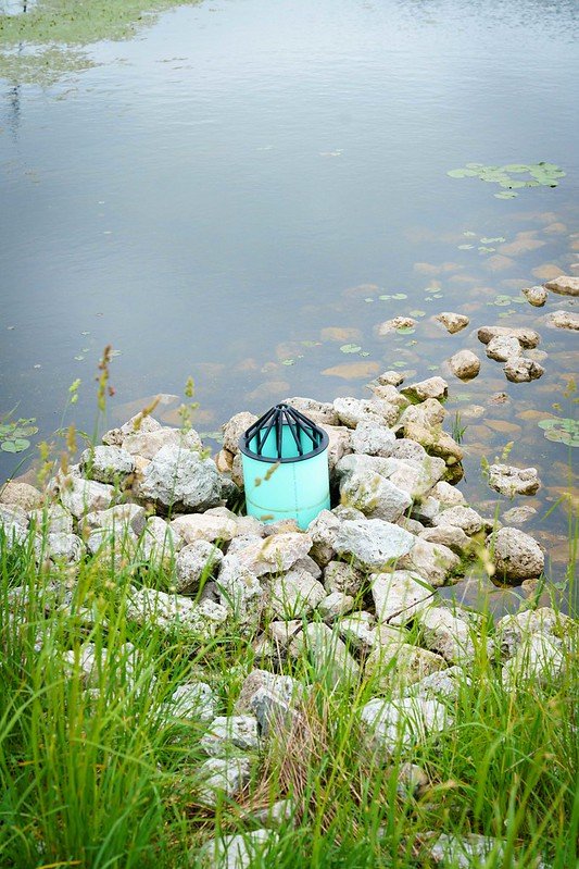
Irrigation Tailwater Return Systems
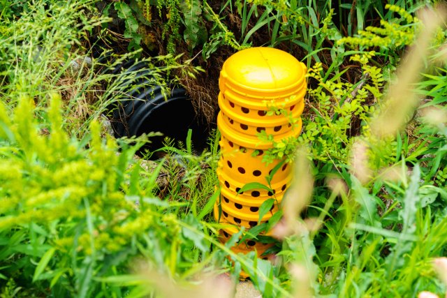
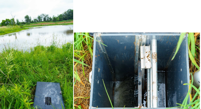
Tailwater return or drainage recovery systems collect, store, and transport irrigation tailwater for reuse in an irrigation distribution system. These systems require a means of collecting the tailwater, such as a storage pond, and a way of returning the water into circulation for future irrigation. These systems are designed to retain runoff on agricultural fields allowing time for pesticides to be adsorbed by or degraded in the soil and reducing the amount of effluent reaching downstream waterbodies. Irrigation tailwater return systems usually include sediment basins, ponds, or other water retention systems, and a water control structure as a component of the system.
In order to be effective for reducing pesticide runoff, irrigation tailwater recovery systems must be appropriately sized to handle all tailwater coming off the field(s). Additionally, the system of conduits and basins that store and return the water into the distribution system must be properly maintained. Stored water must be recycled onto fields or allowed to evaporate.
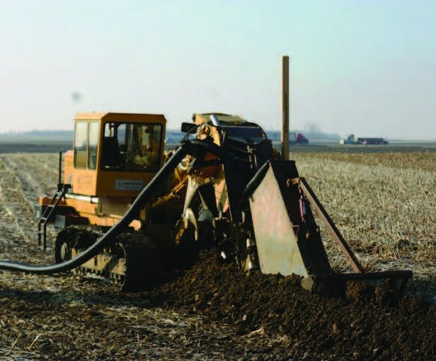
Subsurface or Tile Drainage with Controlled Outlet
Subsurface or tile drainage is an engineered system of drains and pipes installed underneath the field to allow excess surface water to infiltrate into soil and through drains into a pipe system so it can be conveyed off the field. This removes excess water after it has infiltrated into the soil rather than running off as surface water. Subsurface and tile drainage systems can be with or without a controlled outlet. Subsurface or tile drainage without a controlled outlet may be effective for erosion-prone pesticides but are less effective than subsurface or tile drainage with a controlled outlet. Drainage systems without controlled outlets are considered as a separate mitigation measure with a separate mitigation measure description in the section 'Systems that Capture and Runoff and Discharge.'
Controlled outlet structures for subsurface drainage systems usually contain an adjustable weir or other water control system to control the elevation at which water leaves the drainage system and can be adjusted to reduce the flow of water and dissolved pesticides from the field. Subsurface or tile drainage systems can be used in conjunction with other water catchment systems such as sediment control basins, ponds, or tailwater return systems, or they can direct water into a saturation buffer zone.
Subsurface or tile drainage systems must release water into a water-controlled drainage structure such as a water retention system or tailwater return system, or a saturation buffer zone that does not release water into downstream aquatic areas. The drainage structure or area must have enough capacity to capture all drainage water from fields. Drains, pipes, and outlets must be maintained as needed to ensure effectiveness for the life of the drainage system.
Application Methods Where EPA Did Not Identify Runoff/Erosion Mitigations Because Exposure to Non-Target Species is Unlikely from Runoff and Erosion
Soil Injection
Soil injection of pesticides involves application of a pesticide entirely underground, and so runoff/erosion on the surface is unlikely. The chemical must be applied entirely underground through soil. Do not apply more pesticide volume than the soil has capacity to hold, so that runoff does not occur.
Tree Injection
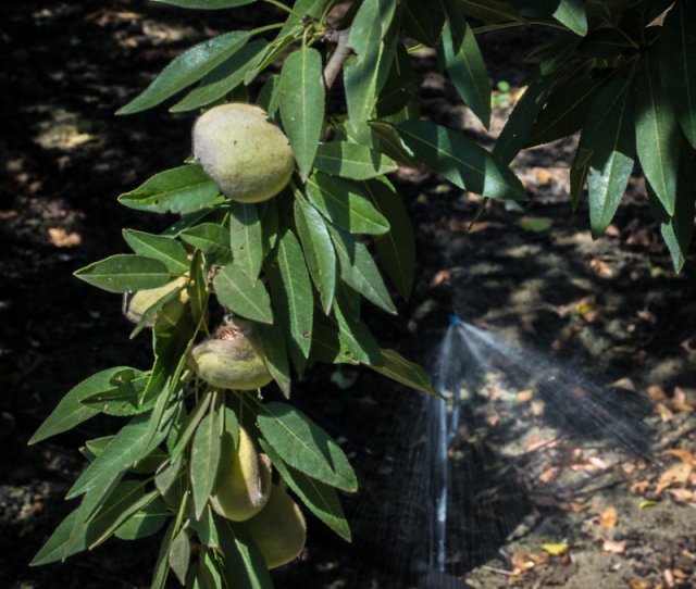
Tree injection of pesticides involves application of a pesticide into a tree with no exposure to nearby soil or vegetation, and so runoff/erosion of pesticides is unlikely. Apply the pesticide through tree injection, and do not allow pesticide to contact the ground or the exterior of the tree.
Chemigation Applied Subsurface and Under Impermeable Plastic Mulch
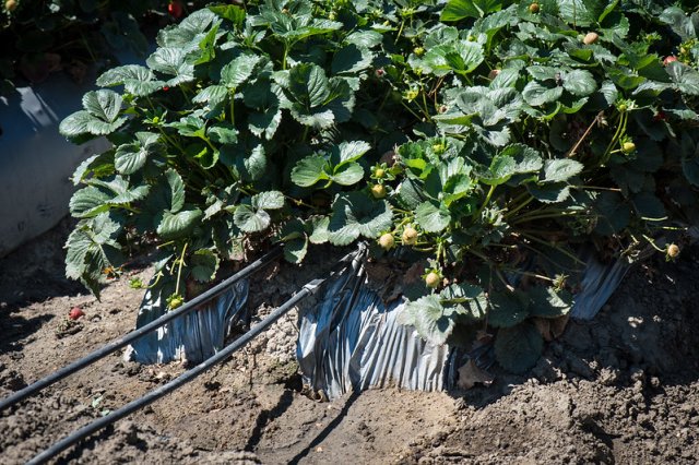
Application of a pesticide through irrigation water (chemigation) under an impermeable layer like plastic mulch delivers the pesticide underground where it is unlikely to move offsite through runoff or erosion, as the plastic provides a barrier to surface movement. Apply the pesticide either through a subsurface irrigation system or through an irrigation system such as drip tape or emitters underneath an impermeable plastic layer. Do not apply more pesticide volume than the soil has capacity to hold, so that runoff does not occur. If applying under plastic, keep plastic on the field for the entire crop season.
Less than 1/10 Acre Treated (<4356 Square Feet) or Spot Treatment (<1000 Square Feet)
Applications to small areas and spot treatments typically use a small volume of pesticide often applied with a backpack sprayer, handheld sprayer, or other small equipment, but under some conditions larger smart technology application equipment can be used. Because of the small application area, offsite movement of pesticides through runoff/erosion is limited. Runoff/erosion mitigation is not required if the application is applied to an area of no more than 1/10 acre (4356 square feet) or is applied as a spot treatment (<1000 square feet) on the field.
Runoff/Erosion Mitigation Relief if the Area at Least 1,000 Feet Down-Gradient from the Treated Farm/Field Contains Only Managed Areas
The amount of pesticide in runoff/erosion decreases with distance from an application area, with higher potential pesticide concentration close to a treated area and lower potential concentrations farther away. Runoff/erosion mitigation is not required if the area 1,000 ft down-gradient of the application area contains managed areas only. Managed areas are defined as:
- Agricultural fields, including untreated portions of the treated field;
- Roads, paved or gravel surfaces, mowed grassy areas adjacent to field, and areas of bare ground from recent plowing or grading that are contiguous with the treated area;
- Buildings and their perimeters, silos, or other man-made structures with walls and/or roof;
- Areas maintained as a mitigation measure for runoff/erosion or spray drift control, such as vegetative filter strips (VFS), field borders, hedgerows, Conservation Reserve Program lands (CRP), and other mitigation measures identified by EPA on the mitigation menu;
- Managed wetlands including constructed wetlands on the farm; and
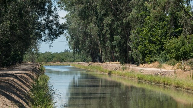
- On-farm contained irrigation water resources that are not connected to adjacent water bodies, including on-farm irrigation canals and ditches, water conveyances, managed irrigation/runoff retention basins, and tailwater collection ponds.
If any part of the area 1,000 feet down-gradient of the application area contains terrestrial or aquatic areas not listed above, then runoff/erosion mitigation is required.
Mitigation Relief Based on Pesticide Runoff Vulnerability
EPA analyzed the runoff vulnerability of counties across the lower 48 states based on rainfall, soil, and other lines of evidence and developed the runoff vulnerability map below (Figure 1) to determine the level of runoff/erosion mitigation needed for each county.
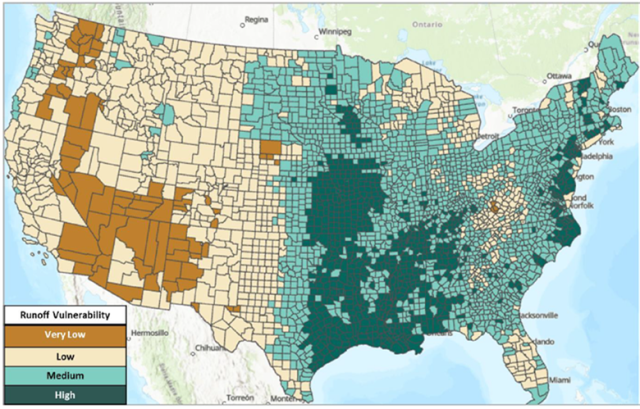
Counties are divided into vulnerability categories with respective mitigation relief points. Counties receiving lower levels of rainfall are less susceptible to runoff/erosion and require less mitigation; therefore, these areas are assigned higher points for mitigation relief. Table 1 describes the mitigation relief points available for each vulnerability category. Click County list (pdf) for a complete list of counties and their respective point designations.
| Vulnerability category | Mitigation Relief Points |
|---|---|
| Very low (brown counties) | 6 |
| Low (yellow counties) | 3 |
| Medium (light blue counties) | 2 |
| High (dark green counties) | 0 |
Other Runoff/Erosion Mitigation Relief Options
Field with Slope ≤3%
Fields that are flat or have minimal slope are less prone to runoff and erosion than sloped fields because water flows at a slower velocity across flat areas, allowing more time for infiltration into the soil. Therefore, EPA is assigning two points if the farm/field has a slope ≤3%. To qualify, the land can naturally have a slope of ≤3% with minimal variation in slope across the application area or be engineered to have a slope of ≤3% across the application area. Several methods can used to engineer a field to ≤3% slope, including land leveling, laser leveling, and land smoothing.
Predominantly Sandy Soils
Coarsely textured soils have a moderately low to low pesticide runoff potential, because water infiltrates efficiently into the soil. Runoff/erosion mitigation relief points are applicable if the farm/field has moderately or predominately sandy soils without a restrictive layer that impedes the movement of water through the soil. Moderately and predominately sandy soils are defined below:
Moderately sandy soils: Fields with 10-20% clay and 50-90% sand (typically loamy sand and sandy loam but can include loam, silt loam, or silt soils if well aggregated, of low bulk density, or contain >30% rock fragments) without a restrictive layer that impedes the movement of water through the soil. These are also known as HSG B type soils.
Predominately sandy soils: Fields with ≤10% clay and ≥90% sand (typically sand but can include loamy sand, sandy loam, loam, or silt loam soils if well aggregated, of low bulk density, or contain >30% rock fragments) without a restrictive layer that impedes the movement of water through the soil. These are also known as HSG A type soils.
If field-specific soil texture data is not available, pesticide users can see USDA’s Web Soil Texture Survey tool to determine soil texture and/or HSG.
To find the soil type for a field using USDA’s Web Soil Texture Survey Tool, start a web soil survey and select the area on the map. In the soil data explorer, select soil properties and qualities, then soil qualities and features, then hydrologic soil group.
Mitigation Tracking
Consistent with typical agricultural practices, EPA expects that mitigation tracking would be done on paper or on an electronic format. Mitigation tracking could help a grower/applicator ensure that they are achieving the number of points to satisfy any labeling requirements/bulletins that include runoff/erosion mitigation. Additionally, tracking the mitigations employed could assist with future planning of farm needs, and is generally aligned with the concepts of agricultural best management practices (commonly known as BMPs). Where a grower/applicator has a well thought out plan for the growing season which includes the tracking of mitigation measures employed, EPA would have increased confidence that measures have been implemented and properly accounted for. Therefore, EPA is assigning one point for any grower/applicator who tracks their mitigations on paper or in electronic format. Working with a runoff/erosion technical specialist or participation in a conservation program is not required to be eligible for this point, and therefore this point is available for any grower/applicator that tracks their mitigation measures.
Follow Recommendations from a Runoff/Erosion Specialist
Grower/applicators may work with a technical expert to develop mitigation plans that work for their field and that are efficacious in reducing runoff and/or erosion. As described above, when a grower/applicator is working with a technical expert who embodies the characteristics below, EPA expects that the mitigation measures would be selected and implemented considering site-specific conditions, including the soil type, field slope, hydrology, local climate, crop(s) grown, pest concerns, drainage systems, irrigation needs, and equipment availability. Specific cropping systems and regions have established norms and practices based on real-world experience that on-site professionals (i.e., technical experts) can account for in the planning process. In this case, EPA expects the efficacy of runoff/erosion mitigation measures would be on the higher end of the range of efficacy. To account for this, EPA identified one runoff/erosion mitigation point available to grower/applicators that work with a runoff/erosion technical expert that meets the characteristics described below. The point for working with the technical expert is in addition to the points for implementing mitigation measures identified in the strategy.
EPA has reviewed available information regarding characteristics that often apply to meet the description of a technical expert. At a minimum, there is usually an education (and a continuing education) and an experience component. Based on this review, the technical specialist must meet the following characteristics:
- Have technical training, education and/or experience in an agricultural discipline, water or soil conservation, or other relevant discipline that provides training and practice in the area of runoff or erosion mitigation technologies/measures; and
- Participate in continued education or training in the area of expertise which should include run off and erosion control; and
- Have experience advising on conservation measures designed to develop site specific runoff and erosion plans that include mitigation measures described in EPA’s Mitigation Website.
EPA has identified the following examples of technical experts: NRCS and similar state or regional level program staff, Certified Crop Advisor, Pesticide Control Advisor, Certified Professional Agronomist, National Alliance of Independent Crop Consultants (NAICC), EnviroCert International, Inc., Certified Professionals in Erosion and Sediment Control, Technical Service Providers, and extension agents. EPA acknowledges that this list is not exhaustive, and the inclusion of an organization should not be construed as an endorsement of any particular group by EPA.
Participate in a Qualifying Conservation Program
Conservation programs provide technical expertise as described above, as well as additional support to grower/applicators. Based on EPA’s review of available information on existing programs, this support may include oversight in the form of a review of design, installation, and upkeep/maintenance plan for the identified mitigations. In addition, the programs typically include documentation demonstrating the site-specific plan meets any program requirements.
While conservation programs are not solely designed to reduce offsite transport of pesticides, several of the same types of mitigations that reduce offsite transport of nutrients and/or soil erosion from an agricultural field also reduce offsite transport of pesticides. Evaluating a field for the purpose of reducing nutrients in runoff and/or soil erosion is likely to result in similar recommended mitigations as those included in the runoff mitigation menu.
EPA has evaluated information provided by stakeholders, and has found that some conservation programs are likely to qualify for 9 relief points once mitigations are implemented on the farm/field. As a result of this evaluation and discussions with U.S. Department of Agriculture and U.S. Fish and Wildlife Services, EPA has amended the identified characteristics of programs to include additional characteristics that would allow EPA to determine that the program qualifies for nine (9) relief points. Growers who participate in an “EPA-Qualified Conservation Program” would effectively be able to meet the maximum of nine (9) mitigation points for EPA’s runoff/erosion mitigation needs for all pesticides when the mitigations are in place before or at the time of pesticide application. The rationale and additional characteristics of a conservation program that are necessary to support designation as an EPA-Qualified Conservation Program are described in more detail in the Final Insecticide Strategy and Ecological Mitigation Support Document to Support Endangered Species Strategies (version 2.0).
For “EPA-Qualified Conservation Programs,” EPA evaluated these programs using the qualifying characteristics described in the Final Insecticide Strategy, Section 3.2.2.6.2 and the Ecological Mitigation Support Document v.2, Section 5.11.2. These characteristics are intended to show how a qualified program, when mitigations are in place before or at the time of application, can achieve at least nine points of mitigation, thereby addressing any potential for potential population-level impacts to listed species from runoff/erosion.
EPA’s first designated “EPA-Qualified Conservation Program”
EPA evaluated USDA-Natural Resources Conservation Service’s (NRCS) Environmental Quality Incentives Program (EQIP) that incorporates NRCS Conservation Program Standard (CPS) 595 Pest Management Conservation System for planning runoff/erosion mitigation for agriculture. USDA-NRCS’s EQIP program is a voluntary, financial assistance conservation program that can address many different resource objectives and, using NRCS CPS 595, can help the grower address the offsite movement of pesticides. To meet the grower’s needs, NRCS develops an EQIP conservation plan that includes the NRCS CPS 595 “General Criteria” and “Additional Criteria” that “mitigates the effects of pest management activities that can impact water quality or other natural resources.” When a grower participates in EQIP with the objective of reducing pesticide runoff/erosion, uses NRCS CPS 595 with the “Additional Criteria” for water quality in the development of the conservation plan, and implements the recommended practices identified in the conservation plan before or at the time of pesticide application, EPA has confidence that the resulting level of mitigation will be consistent with the runoff/erosion mitigation necessary to reduce the likelihood of potential population-level impacts to listed species as a result of pesticide movement through runoff/erosion. Concurrent with the release of the Final Insecticide Strategy, EPA has determined that the USDA-Natural Resources Conservation Service’s (NRCS) Environmental Quality Incentives Program (EQIP), when incorporating NRCS Conservation Program Standard (CPS) 595 Pest Management Conservation System for planning runoff/erosion mitigation for agriculture, is designated as an “EPA-Qualified Conservation Program.
Continued work to develop a process for identifying and providing lists of qualified programs/external parties
EPA will be developing processes to identify, evaluate, and communicate “EPA-Qualified Conservation Programs” to the public. EPA recognizes that it needs to have a system in place to qualify programs/parties to ensure the programs/parties will provide the necessary level of protection. In order to develop those process, EPA will continue discussions with federal partners, state lead agencies, and other stakeholders concerning these efforts and will also seek comment, through Paperwork Reduction Act (PRA) obligations, on any necessary information collections. EPA will engage with stakeholders to ensure that qualified programs are identified. EPA will create a website associated with EPA’s mitigation menu website that will house a list of the EPA-Qualified Conservation Programs. In the interim, conservation programs will be 2 mitigation relief points until they have been designated by EPA as an EPA-Qualified Conservation Program.
Runoff/Erosion Mitigation Options
Application Parameters
Annual Application Rate Reduction
Lower pesticide application rates can result in less runoff because there is a smaller amount of pesticide available to move with water or sediment. Use an annual application rate lower than the maximum annual application rate. Reduced application rates may be achieved by using a lower single application rate or lower number of applications across the application area. Do not apply less than the minimum single application rate if there is one indicated on the label. More points are given for larger annual rate reductions, as a percentage of reduction from the maximum annual application rate. Use an application rate that is high enough to be effective for control of target pest(s) and for resistance management.
Reduction in Proportion of Field Treated
Reduced pesticide application areas can result in less runoff because there is a smaller amount of pesticide available to move with water or sediment. Use equipment that reduces the area of the field treated with pesticide. This may be accomplished by banded applications, spot application, backpack or handheld application, border area treatments, or precision application equipment (including smart sprayers). The application area should be large enough to be effective for control of target pest(s) and for resistance management.
Soil Incorporation
Some pesticide products can be incorporated into the soil at the time of application or shortly thereafter. For those products, distributing them into the soil decreases their ability to move with runoff or erosion, and in some cases, also increases effectiveness of the product.
For products that do not require incorporation, mitigation points are available when the product is incorporated to a depth of at least 1 inch before a runoff producing rain event occurs. Methods of soil incorporation include irrigation (watering-in) and tillage (soil discing, field cultivator, roto-tiller, etc.). If incorporating by mechanical methods (i.e. discing), incorporate within the time required on the product label or before the first runoff rain event occurs. If incorporating by irrigation, watering-in must be completed within 24 hours of application without any runoff occurring.
In-Field Mitigation Measures
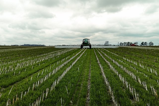
Conservation Tillage
This mitigation measure includes practices such as reduced tillage (strip-till, ridge-till, and mulch-till) and no tillage (no-till, perennial crop). Each practice must achieve at least 30% crop residue covering the soil surface: this residue level must be in place the entire time conservation tillage mitigation points are being considered. Below are more detailed guidelines for these practices.
- No-till: Soil is not disturbed by tillage. Planting or drilling is accomplished using disc openers, coulter(s), and row cleaners. No-till crop production can include rotations of annual crops where tillage is not performed between crops. Perennial crops where tillage is not used are also considered no-till. Perennial crops cannot earn points for no-till production in the year of establishment or renovation if tillage is used but may fulfill the requirements of reduced-till below.
- Strip till: Soil is left undisturbed except for strips up to one-third of the row width. The strip of disturbance may involve residue disturbance or soil disturbance. Planting or drilling is accomplished using disc openers, coulter(s), row cleaners, in-row chisels, or rototillers; cultivation can be used for emergency weed control. Other common terms used to describe strip-till include row-till and slot-till.
- Ridge-till: Crops are planted into a seedbed prepared by scraping off the top portion of the ridge. Ridges are often formed during cultivation of the previous year’s crop. Ridge-till operations consist of planting in the spring and at least one cultivation to recreate the ridges for the next year. Rows remain in the same place each year and any crop residue on the ridges at planting is pushed between the rows.
- Mulch-till: One hundred percent of the soil surface is disturbed by tillage but a uniform layer of crop residue remains on the soil surface. The practice is implemented before or during planting. Tillage tools such as chisels, field cultivators, discs, sweeps, or blades are used.
Reservoir Tillage
Reservoir tillage is a practice where specific tillage tools are used on flat fields to create a depression in the soil between crop rows. These depressions collect precipitation and irrigation water allowing the water to infiltrate into the soil, thereby reducing erosion and runoff. Furrow diking and basin tillage have a similar effect as reservoir tillage and qualify for this mitigation measure. The depressions in the soil must be large enough to accommodate rainfall, and stable enough to remain in place through the growing season.
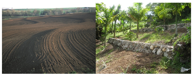
Contour Farming
Contour farming or contour tillage changes the direction of runoff from flowing directly down the slope to across the slope. This can be achieved by implementing ridges or furrows with tillage or by planting the crop (annual or perennial) following the contour of the land. The disruption of downslope flow slows the runoff velocity and allows for more time for runoff to infiltrate the field soils, thereby reducing runoff. This mitigation measure includes practices such as contour farming, contour tillage, contour orchard and perennial crops.
For annual crops, orchards, and perennial crops the direction of rows must be established and maintained as close to the angle of the field contour as possible.
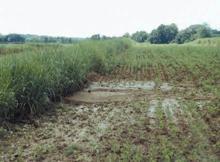
Vegetative Strips - In-Field
Vegetative strips are managed in-field areas of grass or other permanent herbaceous vegetation that intercept and disrupt flow of runoff, trap sediment, and reduce pesticide concentrations in water. Thus, nutrients, pesticides, and eroded soils in the runoff water are filtered through the grass where they are adsorbed by or degraded in the soil, and potentially taken up by the plants. The effectiveness of filter strips to reduce pesticide loading into an adjacent landscape or surface water body depends on many factors, such as topography, field conditions, hydrologic soil group, antecedent moisture conditions, rainfall intensity, properties of the pesticide, application methods, width of the vegetative filter strip, and types of vegetation.
This mitigation measure includes practices such as inter-row vegetated strips, strip cropping or intercropping, alley cropping, prairie strips, contour buffer strips, contour strip cropping, and vegetative barrier (occurring in a contoured field).
To function as a mitigation measure for pesticide runoff/erosion, vegetative strips must be established and maintained such that the application area is immediately upslope of the vegetative strip. Where there is concentrated flow upslope of the vegetative strip, mitigation measures must also be added within the treated area to prevent concentrated flow moving into the vegetative strip. The design and maintenance must consider a lifespan sufficient for multiple growing seasons. Vegetative strip plantings must not contain noxious or invasive species and must be maintained promoting dense growth and upright growth.
Best practices include aligning rows as closely as possible so that they are perpendicular to the slope, use of water bars or berms to break up the concentrated flow and divert concentration flow back into the field, and utilizing reduced tillage practices, especially near the vegetative strip.
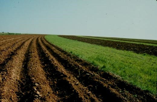
Strip Cropping or Intercropping and Contour Strip Cropping:
In strip cropping, a field is managed where row crops, forages, small grains, or fallow are arranged systematically across a field in equal width strips. Crops are typically arranged so that a strip of grass or forage crop (low erosion potential because of their fibrous root system) is alternated with a strip of row crop (high erosion potential, e.g., corn). This practice differs from contour strip cropping in that rows do not need to be planted along a contour, which allows strip cropping to be used on land without a contour.
Plant alternate strips of high-erosion-potential crops and low erosion potential plants (e.g., hay, small grains, perennial crops, grasses, or other plants with a fibrous root system). A minimum of 50% of the field must be planted with low-erosion-potential crops or sediment trapping cover.
Strip cropping is not as effective if the row crop strips are too wide and must only be implemented on slopes <10%.
In contour strip cropping, a field is managed where row crops, forages, small grains, or fallow are arranged systematically in rows of equal width strips following the contour across a field. Crops are typically arranged so that a strip of grass or forage crop (low erosion potential because of their fibrous root system) is alternated with a strip of row crop (high erosion potential; e.g., corn). The crops are planted across the slope of the land, as in contour buffer strips. This practice differs from contour buffer strips in that it allows for crops to be planted across 100% of the field area.
High erosion potential row crops should be planted on less than half the field and, at a minimum, 50% of the slope must be planted with low erosion potential plants (e.g., hay, small grains, perennial crops, grasses, or other plants with a fibrous root system). The low erosion potential crops reduce erosion, slow runoff water, and trap sediment entering through runoff from upslope areas. This practice combines the benefits of contouring and crop rotation.
Contour strip cropping is not as effective if the row crop strips are too wide and must only be implemented on slopes <10%. Rows must be established and maintained as close to the angle of the field contour as possible.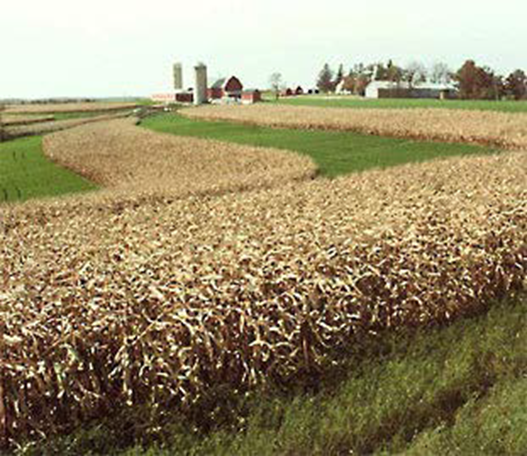
Figure 6. Strip cropping involves growing alternating strips of crops. Photo by U.S. Department of Agriculture. Alley Cropping or Contour Alley Cropping
Alley cropping and Contour alley cropping involves trees or shrubs being planted in single or multiple rows allowing other commodities (i.e., agronomic, horticultural crops or forages) to be planted in the alleys between the rows of trees or shrubs. Contour alley cropping plants in this same pattern but along the contour of a field. The vegetation in the alleys must be established between the trees/shrubs. During the period of establishment, tree/shrubs must be maintained/replaced as needed. Soil erosion must be controlled by vegetative or other means until the alley cropping design is fully functional.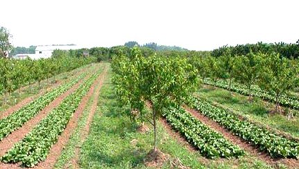
Figure 7. An alley cropping system consisting of a low growing crop grown between orchard row crops. Alley cropping systems usually consist of an orchard or timber crop intercropped with a shorter annual or perennial crop. Photo by U.S. Department of Agriculture. Vegetative Buffer Strips – In-Field
This measure is inclusive of buffer strips, contour buffer strips, prairie strips, contour prairie strips, vegetative barriers, and contour vegetative barriers.
Buffer strips are strips of permanent herbaceous vegetation, primarily of perennials such as grass, alternated with wider cultivated strips that are often also farmed on the contour (perpendicular to the slope).
Vegetative buffer strip widths must be a minimum of 15 feet. Wider distances may be appropriate based on variables such as higher field slope, less permeable soil types, field conditions, climate, and higher erosion potential. Contour buffer strips are unsuitable in fields where irregular, rolling topography makes following a contour impractical.
To ensure maximum performance, the integrity of the buffer must be maintained for the entire width and length, including: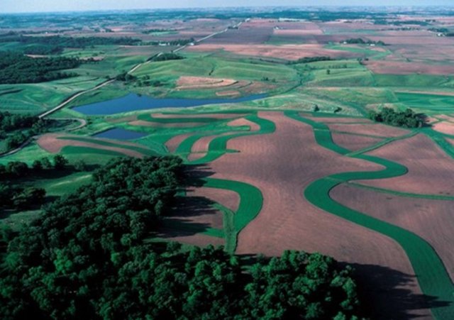
Figure 8. In-field contour buffer strips of vegetation planted along the contour of a sloped field. Photo by U.S. Department of Agriculture. 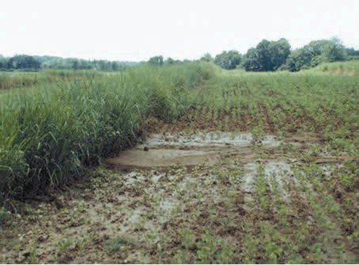
Figure 9. A vegetated barrier contains dense tall grasses adjacent to the field and functions as a vegetative filter strip. Photo by U.S. Department of Agriculture. - The buffer must be harvested or mowed, reseeded, and fertilized as necessary to maintain plant density and vigorous plant growth.
- Vegetation must be kept tall in spring and early summer to slow runoff flow, maximize disruption of concentrated flow, and reduce the chance of damage.
- Regular maintenance must also include inspection after major storms, removal of trapped sediment, and repair of eroding areas.
Terrace Farming
Terraces are described as a stair-stepping technique of creating flat or nearly flat crop areas along a gradient. They can be constructed as earth embankments or a combination of ridge and channel systems. A terrace is built across a slope to intercept and store water runoff. Some terraces are built level from end to end to contain water used to grow crops and recharge groundwater. Others, known as gradient terraces, are built with some slope or grade from one end to the other and can slow water runoff. The application of terraces is not recommended on slopes <2%. Terraces can be constructed with uniform slope widths or uniform slope intervals.
Additionally, an earthen ridge, diversion, or terrace can be constructed across the slope upgrade from a field area to prevent runoff from entering the area or to direct runoff from one area of production to a common runoff collection area.
Construct terraces so that the flat cropped areas have 3% slope or less.
The ends of terraces, including turnrows, must be structured and maintained to prevent concentrated flow from damaging the function of the terrace.
If runoff outflows are necessary, the runoff must be directed to a system such as a grassed waterway, a grade-stabilization structure, a filter strip, water or sediment basin, or other suitable outlet with adequate capacity to handle the runoff and prevent gully formation.
Cover Crop/Continuous Ground Cover
A cover crop is seeded in a narrow row spacing and at close intervals down the row to rapidly develop a vegetative cover that that temporarily protects the ground from wind and water erosion. Common cover crops include cereal rye, oats, triticale, clover, vetch, and winter wheat or combinations of these crops. Cover crops may be used successively after one crop is harvested or relay-planted where the second crop is planted into the first crop before harvest. This mitigation measure considers how the cover crop is terminated (tillage or no-tillage) and the duration of time the cover crop was on the field prior to termination (short or long duration). This mitigation measure includes cover crops, double cropping, and relay cropping.
The cover crop must remain on the field through at least field preparation for planting the cash crop. Cover crops that are terminated with tillage provide some runoff reduction benefit, but less than a cover crop in a field that is not tilled. Spring planted or short duration cover crops not terminated with tillage provide a moderate runoff reduction benefit. Fall planted or long duration cover crops provide the most benefit because they have more time to generate greater biomass, but this benefit is greatly reduced if the cover crop is terminated by tillage. Perennial crops such as perennial forages (e.g., alfalfa), cranberry, or some fruit orchards with year-round vegetation between rows that have continuous cover function similarly to a long duration cover crop because of the continuous vegetative cover and root systems.
- A tilled cover crop is any cover crop that is terminated using a tillage operation or any cover crop where tillage is used between cover crop termination and planting of the subsequent cash crop. Perennial crops with continuous ground cover (e.g. grasses for hay, alfalfa, cranberry) can be considered a tilled cover crop in the year of establishment or field renovation.
- A short duration cover crop is any cover crop that meets the following characteristics: planted in the spring, just before planting a spring cash crop; planted in the fall but, terminated due to winter conditions where there is no active spring growth; or cover crops grown between subsequent short-season crops within a single growing season.
- A long duration cover crop is any cover crop that meets the following characteristics: planted in the fall, overwinters, and grows into spring; or a perennial cash crop with continuous ground cover. For continuous ground cover, maintain vegetation on the field year-round. Perennial crops with continuous ground cover are not considered a long duration cover crop in the year of establishment or field renovation if tillage is used.
Crop insurance allows for cover crop flexibilities and producers should be mindful of those flexibilities and ensure that a cover crop fits within the guidelines or rules of their insurer.
Planting directly into a standing, mowed, or rolled cover crop will provide the greatest benefit for reducing runoff.
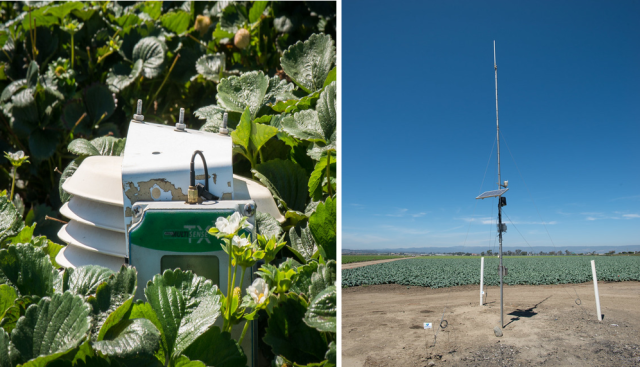
Irrigation Water Management
To receive points for this mitigation measure, irrigation water management on the field must control the volume, frequency, and rate of irrigation water applied to a field such that no irrigation-induced runoff from the field is generated, or the field must be non-irrigated.
For irrigated fields, fields must have an irrigation management strategy that includes the daily water use of the crop, the water-holding capacity of the soil, and the lower limit of soil moisture for each crop and soil. Additionally, when implementing this measure, one must be able to measure the amount of water applied to the field and factor in potential rainfall from precipitation forecasts. Proper irrigation scheduling depends on daily accounting of the cropland field water budget.
The tools required to complete this budget include water measuring devices (e.g., irrigation water meter, flume, or weir) and soil and crop water use data. The method of water application should be suitable to the site-specific conditions of the farm (slopes, soils, types of crops, climate, etc.). The irrigation water management system must also be properly designed, maintained, and operated.
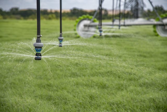
- General irrigation management includes center pivots, sprinklers (overhead, wheel line, wheel move, laterals, hand-set, permanent, etc.), above ground drip tape, drip emitters, micro-sprinklers, flood, and furrow irrigation. To receive points for center pivot, sprinkler, flood, or furrow irrigation, an irrigation management technology such as soil moisture sensors or evapotranspiration meters must be utilized. To receive points for flood or furrow irrigation, irrigation systems must use runoff reducing technology such as computerized hole selection and surge values.
- Sub-surface irrigation includes below ground drip tape or below an impermeable tarp/plastic. In irrigation systems where water is applied to the crop below the soil surface, there should be minimal runoff or erosion occurring, maximizing the efficacy of these practices for runoff and erosion mitigation. Chemigation applied to the subsurface and under non-permeable plastic mulch do not require runoff/erosion mitigation and is discussed further under the section titled “Application Methods where EPA did not Identify Runoff/Erosion Mitigations because Exposure to Non-Target Species is Unlikely”.
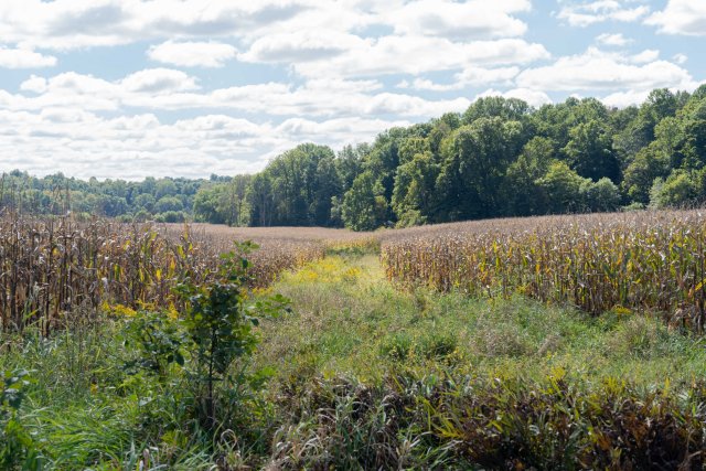
- Non-irrigated production includes non-irrigated fields/dryland farming. Without irrigation, there is no potential for irrigation-induced runoff. To classify as non-irrigated/dryland farming, there must not be irrigation on the field at any time of the year.

Anionic Polyacrylamide (PAM)
Anionic PAM is a soil conditioner that is typically used to reduce runoff and erosion in exposed soil by stabilizing soil aggregates as well as flocculating suspended particles. Anionic PAM is available in a variety of formulations. To receive mitigation credit for this measure, the anionic PAM must:
- Be of the anionic type that meets acrylamide monomer limits of ≤ 0.05 percent.
- Have a charge density of 10 to 55 percent, by weight.
- Have a molecular weight of 6 to 24 Mg/mole.
Cationic forms of PAM are toxic to aquatic taxa and must not be used.
Apply anionic PAM according to the manufacturers recommended application rate which may need adjustments for soil properties, slope, and type of irrigation used. Applications of anionic PAM should be made during the first irrigation event and after any soil disturbing activities (e.g. tillage). Growers may also achieve mitigation credit for this measure when anionic PAM is applied in a manner consistent with NRCS Conservation Practice 450.
Do not apply anionic PAM to non-irrigation water.
Mulching with Natural and Artificial Materials
Natural and artificial mulches must be applied in a manner that provides a minimum of 70 percent ground cover. The minimum depth of chipped mulch materials must be 2 inches ensuring it will remain in place during heavy rain or winds. Vegetation-based mulches usually have a carbon to nitrogen ratio (C:N) greater than 20:1. If mulch needs to be held in place, appropriate measures must be used (e.g., tacking, crimping) so that the mulch remains on the field. Periodic inspections are required to ensure the mulch remains intact and to identify when repairs/reinstallations are needed.
Erosion Barriers
Wattles are fiber-filled (e.g., straw, coir) rolls in a mesh netting designed to control soil erosion by reducing water flow velocity thereby enhancing the capture of sediment through improved infiltration. Typically, wattles are held in place by wooden stakes and applications can be seen at construction sites and post-forest fire remediation sites where sloping occurs but can also be used as perimeter control surrounding fields and waterbodies. Wattles are often a temporary measure used in recently disturbed areas where vegetation has not yet established or in areas undergoing erosion remediation. Wattles should be placed on slopes such that they intercept concentrated flow and be with high enough frequency and sized to ensure that runoff does not flow over the top of them. Wattles should also be staked firmly into the soil, so water does not flow underneath them. Remove sediment as needed to intercept water flow. Compost filter socks function similarly to wattles.
Silt fences are mesh fences which can be temporary or permanent, and function similarly to wattles by capturing sediment and reducing flow velocity. Silt fences should be placed to intercept concentrated flow and be tall and long enough that concentrated flow is interrupted and does not flow over, underneath, or around them. Remove sediment as needed to maintain function.
Adjacent to the Field Mitigation Measures
Grassed Waterway
Grassed waterways are natural or constructed vegetated channels designed to direct surface water, allow flow at non-erosive velocities and provide a stable outlet (e.g., another vegetated channel, an earth ditch). In concentrated flow areas, grassed waterways can act as an important component of runoff and erosion control by slowing the flow of water and allowing for increased water infiltration into the soil. Grassed waterways are often planted with perennial grasses such as bermudagrass, Timothy, tall fescue, perennial ryegrass and Kentucky bluegrass.
Establish grassed waterways in areas that are susceptible to concentrated flow (shallow channelized flow leading to gullies and rivulets). Grassed waterways must be downslope of the application area. Plant perennial native grasses (where possible) using broadcast seeder or seed drill. Other plant species, with the exception of invasive or noxious plants, can be used.
Grassed waterways must be regularly maintained and operated to maintain waterway capacity, vegetative cover, and outlet stability. Do not damage vegetation within the grassed waterway by machinery, herbicides, or erosion. Grassed waterways must be protected from concentrated flow during establishment by using runoff diversions which can include silt fences, mulching, hay bale barriers, or netting to stabilize grade during vegetation establishment and after disruption or damage. These runoff diversions may be temporary or permanent, depending on material. Diversions should be removed or modified following establishment to allow water to flow through the waterway.
Grassed waterways must be inspected regularly, especially following heavy rains. Any damage or disruptions must be repaired as soon as possible and before making pesticide applications by filling, compacting, and reseeding. Remove sediment deposits to maintain capacity of the grassed waterway. Maintain a healthy, dense, and functional vegetated strip. Runoff outflow must be directed to a system such as another grassed waterway, an earthen ditch, a grade-stabilization structure, a filter strip, water or sediment basin, or other suitable outlet with adequate capacity to handle the runoff and prevent gully formation.
Vegetative Filter Strips – Adjacent to the Field
Vegetated filter strips are managed in- or off-field areas of grass or other permanent herbaceous vegetation that intercept and disrupt flow of runoff, trap sediment, and reduce pesticide concentrations in water. Generally, a filter strip can vary in width but are typically 20 to 120 feet wide. Vegetative filter strips are usually planted with dense grasses.
To function as a mitigation measure for pesticide runoff/erosion the vegetative filter strip must be established and maintained such that the application area is upslope of the vegetative filter strip. Where there is concentrated flow upslope of the filter strip, mitigation measures must also be added within the field to prevent concentrated flow moving into the filter strip. The design and maintenance must consider a lifespan sufficient for multiple growing seasons. Filter strip vegetative plantings must not contain noxious or invasive species and must be maintained as appropriate to encourage dense growth and maintain upright growth. Vegetative filter strips must be a minimum of 20 feet wide, measured from the edge of the field to the outer edge of the filter strip. Best practices include aligning rows as closely as possible so that they are perpendicular to the slope, use of water bars or berms to break up the concentrated flow and divert concentrated flow back into the field, and utilizing reduced tillage practices, especially near the vegetative strip.
- Vegetative Barrier
Vegetative barriers are narrow, permanent strips of stiff-stemmed, erect, tall, and dense vegetation established in parallel rows on the contour of fields to reduce soil erosion and sediment transport. These buffers function similar to contour buffer strips and may be especially effective in dispersing concentrated flow, thus increasing sediment trapping and water infiltration. Because the vegetative barrier, typically comprised of grasses, is established on the contour, runoff is restricted, reducing sheet flow and erosion from concentrated flow. The grass slows runoff, helping the water soak into the soil and reducing erosion. The specific recommendations for establishing the vegetative barrier vary from site to site.
Barrier widths can vary, and efficacy is influenced by variables such as slope, soil type, field conditions, climate, and erosion potential. Vegetative barriers must be a minimum of 20 feet wide. To ensure maximum performance, the pesticide user must maintain the integrity of the barrier for the entire width and length. The barrier must be harvested or mowed, reseeded, and fertilized as necessary to maintain plant density and vigorous plant growth. The maintenance schedule must keep vegetation tall in spring and early summer to help slow runoff flow, maximize disruption of concentrated flow, and reduce the chance of structural damage.
Regular maintenance must also include inspection after major storms, removal of trapped sediment, and repair of eroding areas.
- Field Border
A field border is defined as a strip of permanent vegetation established at the edge of a field. The application area must be upslope of the field border. Establishment and maintenance of the field border and any land immediately upslope of the border must aim to eliminate or significantly reduce concentrated water flow and promote surface sheet flow runoff.
To prevent significant erosion within a field border, concentrated flow must be broken up or redirected. This may be achieved by aligning the field border and planting rows as closely as possible in a direction that is perpendicular to the slope. Use of water bars or berms to divert concentrated flow back into the field is another tool to break up the concentrated flow and promote sheet flow into the border.
A field border must have a minimum width of 20 feet for the purpose of reducing pesticides in runoff and be composed of a permanent dense vegetative stand. This stand is often composed of stiff upright grasses. Non-woody flowering plants may also be included in a well-managed border.
Inspect field borders after major storms and repair eroding areas.
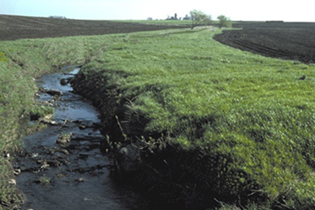
Vegetated Ditch
A vegetative drainage ditch (or vegetated ditch bank) is a sloped channel, planted with vegetation (grass or otherwise) that transports surface water at such a rate that it does not erode soil to a stable outlet. The vegetated ditch must be located downslope of the application area.
The capacity of the vegetated ditch bank must accommodate peak runoff volume expected from a 10-year frequency, 24-hour duration storm. Vegetation must be selected such that the vegetation will achieve an adequate density, height, and vigor, and is durable enough to withstand the peak runoff volume expected. Maintenance must include ensuring a healthy grassed or vegetative surface within the vegetated ditch bank, inspections after major storms and repair to damaged areas, as well as removal and redistribution of excess sediment back to the field.
Riparian Area
Non-flooded riparian areas are vegetated buffers between a field and a water body that reduce erosion while maintaining water quality in the waterbody. Vegetation can consist of herbaceous or woody vegetation and must be tolerant to intermittent flooding and saturated soil. Riparian areas must be managed until established in the transitional zone between a field and an aquatic habitat. Similar to vegetative filter strip, riparian buffers must be a minimum of 20 feet wide. Riparian buffers should only be used where channel and stream bank stability are adequate to support this practice.
Constructed and Natural Wetlands
Wetlands and flooded riparian areas are similar to non-flooded riparian areas but are permanently or seasonally flooded. Wetland or flooded areas can be constructed or a naturally wet area that is managed to maintain vegetation and water quality. Vegetation can be of many types but must be tolerant of the flooded conditions. Vegetative plantings must not contain noxious or invasive species and be appropriate for site conditions. Areas must be downslope of the application area, maintained as appropriate, and have sufficient capacity to accommodate runoff from all fields draining to the wetland or flooded area.
Terrestrial Habitat Landscape Improvement
Terrestrial habitat and landscape improvements are permanent or semi-permanent vegetated areas designed for wildlife habitat or other purposes such as reducing erosion or runoff. They function similarly to vegetative filter strips in that they intercept and disrupt flow of runoff, trap sediment, and reduce pesticide concentrations in water, but they can have a wide variety of vegetation. Vegetation types could include native grasses, plants that are forage for wildlife or pollinators, shrubs, or trees. Habitat or wildlife improvement areas must be a minimum of 20 feet wide. They must be established downslope of the pesticide application area and be maintained such that they eliminate or substantially reduce concentrated flow and promote surface sheet flow runoff. Where there is concentrated flow upslope of the terrestrial habitat area, mitigation measures must also be added within the treated area to prevent concentrated flow moving into the terrestrial habitat area. Vegetative plantings must not contain noxious or invasive species and must be maintained as appropriate.
Filtering Devices with Activated Carbon or Compost Amendments
Carbon amendments used in filters, sleeves, or socks can remove pesticides from runoff when placed in receiving drains or water outlets of water leaving agricultural fields. This does not reduce the amount of water runoff leaving a field but can reduce the concentration of pesticides in that runoff, depending on the type of pesticide.
Place carbon amended filters or other devices in drains or outlets so that runoff water flows through the filter. Use a sufficient quantity to accommodate the expected amount of water. Maintain runoff and replace filters as necessary to maximize filtering efficacy. Acceptable carbon amendments for use in filters include activated carbon or compost.
Systems that Capture Runoff and Discharge
Water Retention Systems
Several mitigation measures can act to capture or retain water and/or sediment that runs off of agricultural fields. Growers who wish to use any of these mitigation measures must follow all state and local laws and regulations.
- Water and Sediment Control Basins
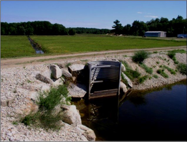
Water and sediment control basins are earthen embankments, or a combination of ridges and channels constructed across the slope of minor watercourses to form a water retention basin and sediment trap with a stable engineered outlet. The purpose of the practice is to collect runoff, eroded sediment, and other debris. Thereby in effect these increase the holding time to allow for degradation of pesticides, reduce the velocity of runoff leaving the field and allow sediment to settle out. Catch basins and sediment traps function similarly.
Construct water and sediment control basins in areas susceptible to gully erosion. To increase efficacy, plant and maintain a healthy vegetated surface within the interior of the basin. Inspect basins after major storms and repair damaged areas. Remove and dispose of, or reuse, excess sediment as appropriate.
Water and sediment control basins can be used in conjunction with, or as a component of, other runoff and erosion mitigations practices including:- Subsurface/Tile drainage: This is a practice where an underground pipe or pipe system is installed to collect and move excess water from a field.
- Tailwater recovery systems: These systems are intended to collect, move, and temporarily store runoff water so that it can be reused later.
- Drainage water management: This conservation practice involves managing the drainage volume and water table elevation by regulating the flow from a surface or subsurface agricultural drainage system.
- Water Retention Ponds
Ponds are similar in function to sediment basins, as they can collect runoff and allow time for the sediment to settle from sediment-laden runoff drained from a field.
Ensure that failure of any dam will not result in loss of life, damage to homes, commercial or industrial buildings, main highways, or railroads, environmental damage, or interruption of the use or service of public utilities.
When constructing ponds for runoff and erosion control, ensure that the pond has sufficient capacity to accommodate runoff from all fields draining to the pond.
Maintain pond edges, embankments, and outlets to ensure appropriate function for the life of the pond.
Periodically remove excess sediment from pond.

Subsurface Drainages and Tile Drainage Installed without Controlled Drainage Structure
Subsurface or tile drainage is an engineered system of drains and pipes installed underneath the field to allow excess surface water to infiltrate into soil and through drains into a pipe system so it can be conveyed off the field. This removes excess water after it has infiltrated into the soil rather than running off as surface water. Subsurface and tile drainage systems can be with or without a controlled outlet. Subsurface or tile drainage without a controlled outlet may be effective for erosion-prone pesticides but are less effective than subsurface or tile drainage with a controlled outlet. One mitigation point can be achieved when a subsurface or tile drainage system is installed without controlled drainage. Subsurface or tile drainage systems with controlled outlets are considered as a separate measure and when installed do not require additional runoff/erosion mitigation.
Subsurface drains, pipes, and outlets must be installed and maintained as needed to ensure effectiveness for the life of the drainage system. Subsurface or tile drainage without a controlled outlet may be used in conjunction with water control structures or water retention systems but are not required to and do not need to meet the requirements for a controlled outlet.
Other Runoff/Erosion Mitigation Measures
Using mitigation measures from multiple categories
Combining multiple types of runoff reduction methods can increase the efficacy of each type by acting on multiple factors in pesticide runoff: decreasing the amount of pesticide that leaves the application area, slowing or catching runoff at the edge of the application area, and catching water or sediment that does leave the application area. In order to qualify for 1 mitigation point, use mitigation measures from at least two of the following categories: on-field mitigation measures, adjacent to the field mitigation measures, and water retention systems.
Spray Drift Buffer Reduction Options Sufficient to Reduce Exposure Such That Potential Population-Level Impacts are Unlikely
Reduce boom length (airplane applications only)
A 65% reduction in the downwind ecological drift buffer can be made when:
- the label specifies a maximum wind speed of 10 miles per hour, AND
- the Sustained Wind Speed, as defined by the National Weather Service (standard averaging period of 2 minutes) registers between 3 and 10 miles per hour, AND
- the boom length is 50% of the wingspan.
A 50% reduction in the downwind ecological drift buffer can be made when:
- the label specifies a maximum wind speed of 15 miles per hour, AND
- the Sustained Wind Speed, as defined by the National Weather Service (standard averaging period of 2 minutes) registers between 10 and 15 miles per hour, AND
- the boom length is 50% of the wingspan.
Wind speed must be measured at the release height or higher, in an area free from obstructions such as trees, buildings, and farm equipment.
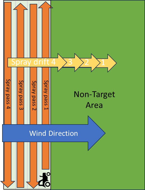
Reduction in Proportion of Field Treated (# of airplane/helicopter/ground equipment passes)
In general, pesticides are applied to a field or orchard (treated area) by making multiple passes (e.g., of an airplane or tractor) in parallel rows of that treated area. With each pass, spray drift may move from the treated area to the non-treated area in the direction of the wind. Pesticide accumulates in the non-target area from each pass. The more passes or rows that are treated, the greater the pesticide accumulation in the non-target area (Figure 37).
Downwind Drift Barriers
Downwind drift barriers can be either be manmade or managed structures, or naturally occurring areas of forests/woodlots/riparian/shrubland. Each of these categories have unique use characteristics and associated buffer reductions.
Windbreaks/Hedgerows/Shelterbelts
Windbreaks, hedgerows, and shelterbelts (described as “windbreaks” in this description) are structures adjacent to the treated area that are effective at reducing spray drift transport (downwind of the application). Windbreaks function by reducing windspeed, intercepting spray droplets and ultimately reducing the amount of spray droplets and distance they travel. Windbreak structure (i.e., height, width, density, composition, length, orientation, and continuity) determines its effectiveness. EPA has identified two types of windbreak structures that have different levels of effectiveness and thus different % reductions in the ecological drift buffer distance.
Both basic and advanced windbreaks between the application site and non-managed area must be present and meet the following criteria for 50% and 75% wind-directional buffer distance reductions, respectively:
- The windbreak or shelterbelt must be downwind between the pesticide application and the non-managed area.
- The windbreak or shelterbelt must run the full length of the treated area with no significant breaks in the vegetation.
- The windbreak or shelterbelt foliage must be sufficiently dense such that the non-managed area is not visible from the upwind side at the time of application.
- The windbreak or shelterbelt must be planted according to local/regional/federal conservation program standards; however, no state or federally listed noxious or invasive trees or shrubs should be planted.
- The windbreak or shelterbelt must be maintained such that their functionality is not compromised.
- For basic windbreaks (50% reduction)
- The height of the trees in the windbreak or shelterbelt must be at the same height or above the release height of the application.
- The windbreak must have a minimum of one row of trees and/or shrubs or a 4-foot wide strip of non-woody vegetation.
- A semi-permeable manmade structure, curtain, or netting that is raised prior to application can be used instead of a windbreak or shelterbelt. This structure must be downwind between the pesticide application and the non-managed area, cover the entire distance of field adjacent to non-managed area, and at the same height or higher as the release height of the application.
- For advanced windbreak (75% reduction)
- The height of the trees in the windbreak must be at a height that is at least twice as high as the release height of the application.
- The windbreak must have a minimum of two or more rows of trees and/or shrubs with a mixture of vegetation types (e.g., trees, shrubs, herbs), or that have 4 or more meters of depth for herbaceous (non-woody) vegetation.
A semi-permeable manmade structure, curtain, or netting that is raised prior to application can be used instead of a windbreak. This structure must be downwind between the pesticide application and the non-managed area, cover the entire distance of field adjacent to non-managed area, and at a height that is at least twice as high as the release height of the application.
Forests/Woodlots/Riparian/Shrubland Areas
Riparian/forested/shrubland/wooded landscapes also provide reductions in spray deposition via the same mechanisms described above for windbreaks/hedgerows, but are typically naturally occurring. To qualify for buffer reduction riparian/forests/woodlots/shrubland must be greater or equal to 60 feet in width, be of a height 2x or greater than the release height, and must be present along the entire downwind edge of the application area.
Relative Humidity
Relative humidity (RH) is a measure of moisture in the air relative to ambient air temperature. It is generally understood that lower RH increases the evaporation rate of spray droplets (Sezen and Gungor, 2023), thus making large droplets smaller over time and impacting spray drift.
EPA identified a 10% buffer reduction for aerial and ground applications where RH is 60% or greater at the time of application. Approximately 10% difference in deposition is observed at the maximum aerial (300 ft) spray distance when going from 40 to 60% RH; however, the decrease is even higher when going from 20% to 60% RH. Large parts of the country are expected to have a RH >60% in the morning but a RH <60% in the afternoon. This means that buffer reduction would be contingent on time of day in these areas and that applicators should plan to conduct their field edge applications in the morning (i.e., the part of day with higher humidity) if they intend to leverage the high humidity buffer reduction.
Adjuvants (drift reducing agents)
Adjuvants are non-pesticidal chemicals that may be included in pesticide formulations or added to tank mixtures. Adjuvants have a variety of purposes, including improving performance of the pesticide in controlling pests and reducing spray drift. Types of adjuvants that are available to help reduce drift include oil and polymer-based adjuvants. Spray drift retardants work by increasing the sizes of spray droplets and reducing the amount of fine droplets that are more prone to drift. The concentration of adjuvant in the tank mix influences the effectiveness of spray drift reduction.